Baty Vision Systems – VuMaster 2D Manual / 2D CNC
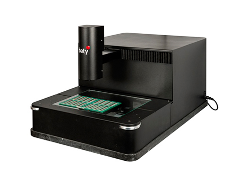
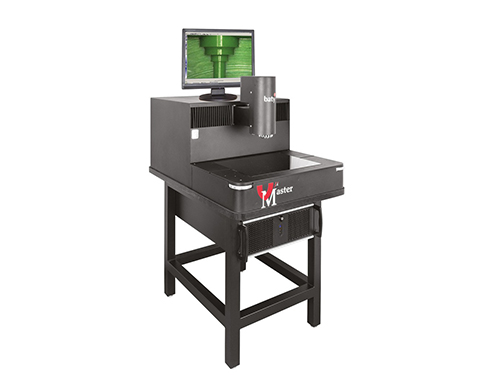
VuMaster is a 2D vision system with a massive difference.
Due to its innovative absolute 2D scale system, the newly designed VuMaster does not have a conventional moving stage or encoders – just a floating measuring camera that moves anywhere in the measuring range. The result is fast, accurate, ‘non contact’ measurement over a much larger measuring range – 400mm x 300mm to be exact!
Because the camera moves and the part stays still, there is often no need for expensive and time consuming work holding devices.
VuMaster is either operated manually or inspection routines can be recorded and stored. When played back, these ‘programs’ guide the operator through a pre-defined inspection procedure recreating the same lighting conditions and using ‘Video Edge Detection’ to automatically ’capture’ feature data.
Finally, a report is generated in the form of a fully dimensioned drawing of the measured part.
Features
- Large 400mm x 300mm measuring range
- Sturdy construction with a granite base
- Supplied with Fusion 2D vision software
- Colourmap measuring technology
- Programmable collimated profile lighting
- Teach and repeat part programming
- Advanced video edge detection
- Digital zoom
- Supplied with stand, PC and monitor
- Programmable segmented LED surface ring light
- Motorised autofocus
- Image grab
- Auto inspection playback
- CNC and Manual models available
Baty’s PC based Fusion Touch software is powerful and easy to use. The touch screen user interface minimises keyboard use and the need for multiple toolbars. The result is an intuitive touch screen software package that enables the user to produce a fully dimensioned drawing of the measured part in minutes!
Other standard reports include tabulated results and multiple part reports all of which can be exported to Excel®.
Video Edge Detection
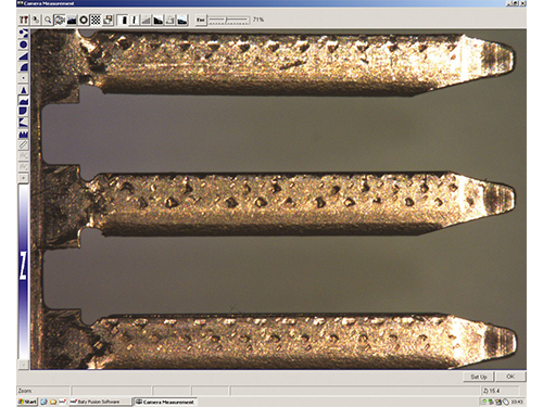
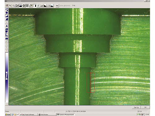
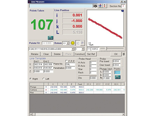
Video edge detection (VED) ensures a repeatable result without relying on the skill of the operator. Hundreds of data points can be taken in an instant to calculate standard geometric features. Standard VED tools include arc, circle, line, point, focus and curve.
Profile Scanning
The curve tool automatically traces the profile of an undefined part. The resulting data-point cloud can then be compared to a pre-toleranced DXF master for best fit analysis. Once ‘fitted’ the data points appear red or green to indicate whether in tolerance. In addition to best fit, conventional dimensions can also be applied to the scan.
SPC Included
Baty Fusion software will also display SPC batch information for multiple components. Information given includes maximum value in batch, minimum value, user definable sigma value, CP and CPK value, mean shift and also plots two different charts of the batch data. SPC data can also be exported to Excel™ for further analysis.
Dimensioned Part View
Measured results are displayed in the form of a fully dimensioned drawing. Dimensions within the specified tolerance are shown in green whilst dimensions out of tolerance are shown in red for immediate visual status of the measured part.

